
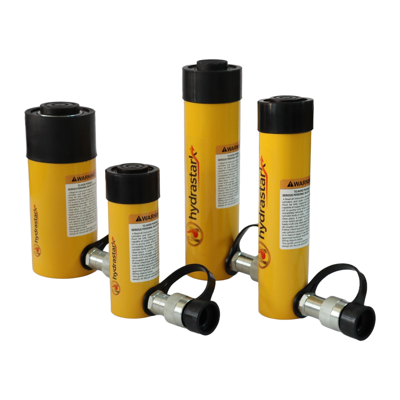
Selecting the correct high-pressure hydraulic cylinder requires balancing force requirements, stroke length, structural geometry, and hydraulic flow. When lifting heavy loads under 700 Bar (10,000 PSI) pressure, understanding the engineering dimensional diagram and port configuration is vital to ensure mechanical stability and seamless tool interchangeability.
1. Decoding the Hydraulic Cylinder Technical Diagram
Every industrial hydraulic cylinder diagram defines five critical geometric boundaries that govern machine installation and stroke travel:
- Dimension A (Collapsed Height): The overall tool length when the piston is fully retracted. This dictates minimum starting clearance in tight jacking pockets (such as bridge bearings or heavy machine bases).
- Dimension B (Extended Height): Maximum overall length at full rated stroke. Total Stroke = Dimension B - Dimension A.
- Dimension D (Outside Diameter): The cylinder barrel envelope diameter, dictating radial clearance between adjacent structural beams or foundation anchors.
- Dimension E (Cylinder Bore Diameter): The internal pressure chamber diameter. Internal Bore Area (cm²) multiplied by 700 Bar hydraulic pressure determines the maximum theoretical tonnage output.
- Port Threads & Fluid Couplers: Standard industrial ports utilize 3/8" NPT female threads mating with high-flow quick couplers.
2. Sizing Calculations: Theoretical Force vs. Practical Safety Margins
A frequent error among field contractors is sizing hydraulic cylinders at exactly 100% of the calculated dead load. Hydraulic systems should always maintain an engineered buffer:
Force (kN) = Effective Piston Area (cm²) × Pressure (Bar) ÷ 10
Rule of Practice: Size cylinders at 120% to 125% of maximum static load to accommodate dynamic center-of-gravity shifts during multi-point lifting.
3. Single-Acting vs. Double-Acting vs. Mechanical Lock Nut
Different industrial tasks demand distinct hydraulic actuation modes:
| Cylinder Type | Return Mechanism | Primary Application | HydraStark Equivalent |
|---|---|---|---|
| General Purpose (HSC) | Heavy-duty internal spring | Standard industrial shop presses, lifting | Enerpac RC-Series Direct Replacement |
| Hollow Plunger (HSCH) | Spring return / Center hole | Cable tensioning, pull rods, bush extraction | Enerpac RCH-Series Equivalent |
| Mechanical Lock Nut (HSC-LN) | Gravity / Hydraulic Return + Lock Nut | Prolonged bridge jacking, structural holding | Enerpac CLL / RACL Equivalent |
4. Sizing Matrix & OEM Cross-Reference Parity
HydraStark industrial hydraulic cylinders are precision-machined to match standard collar threads (e.g. 2-1/4"-14 UNS, 3-5/16"-12 UN) and base mounting holes. This enables direct installation into existing fixtures without re-machining mounting plates or discarding proprietary accessories.
Featured High-Pressure Cylinder Solutions
Review complete CAD blueprints, stroke options, and load tables: